Basic HTML Version


Ecrin v4.12 - Doc v4.12.02 - © KAPPA 1988-2009
Amethyste Guided Session #1
• Ame
GS01 - 5/19
B01.2 • Making a Well Sketch
It is possible to associate a well sketch to the geometrical description of the well. This will only
be qualitative information as it will not be used further in subsequent calculations.
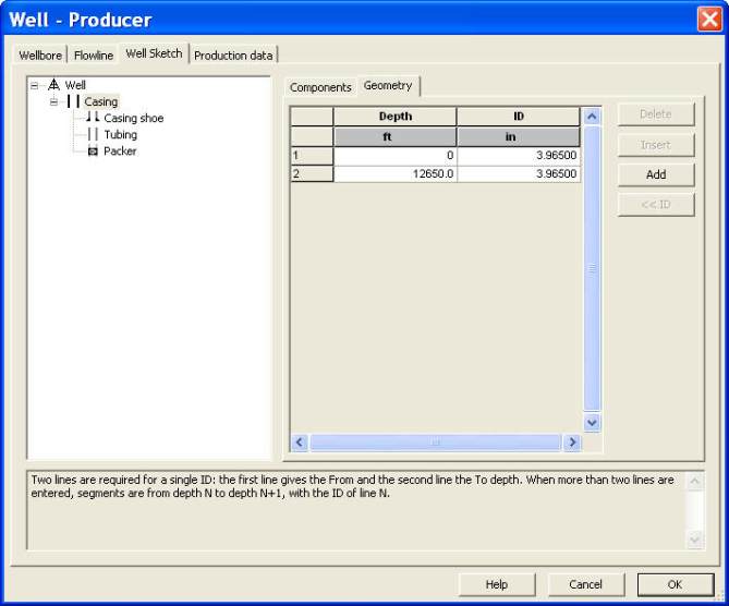
Select the Well Sketch tab and create a well sketch by dragging the elements as follows, from
the components library on the right to the tree view on the left:
-
Add a casing to the wellsketch by selecting the ‘casing’ element in the components
library on the right, and dropping it on the ‘Well’ node in the tree view on the left. This
creates a ‘Casing’ node below the ‘Well’ node.
-
Add a casing shoe by dropping the corresponding element on the ‘Casing’ node.
-
Add a tubing by dropping the corresponding element on the ‘Casing’ node.
-
Add a packer to seal the tubing-casing annular, by dropping the corresponding element
on the ‘Casing’ node.
At the end of this operation the well sketch is designed, but its elements are missing their
geometrical definition. Activate the geometry tab on the right. Select each element in the tree
view on the left, and enter the following geometrical information:
-
casing ID:
3.965 in
from
0
to
12650 ft
-
casing shoe ID:
4.5 in
at
12650 ft
-
tubing ID:
2.441 in
from
0
to
8779 ft
-
packer:
from
8500
to
8700 ft
(not realistic length but ensures a clear display)
Fig. B01.3 • Making the well sketch
When pressing OK, the well sketch plot is created as well as the well geometrical information
entered in the Well geometry dialog (see Fig. B01.4 below). Note that to obtain a similar
figure, the ‘deviation’ and ‘tubing roughness’ plots, given by default, were removed with a drag
of the plot title bars outside of the main plot window (a hand appears when hovering on the
plots title bars).