Basic HTML Version


Ecrin v4.12 - Doc v4.12.02 - © KAPPA 1988-2009
Amethyste Guided Session #1
• Ame
GS01 - 4/19
It is used to enter wellbore data, flowline data, create a well sketch and load some production
data in terms of rate and pressure if available.
In our example, we will study the flow in the wellbore and disregard the flowline section. In the
Wellbore tab, we enter the roughness
0.0006 in
and the bottom hole depth
12650 ft.
By convention, all measured depths (MD) along the wellbore are counted positive, starting
from the wellhead down to the bottom hole. If a flowline is defined, all measured depths along
the flowline are counted negative, starting from the wellhead up to the flowline top.
The fluids are flowing out of the reservoir into the casing section, then into the tubing. This is
equivalent to a fluid flow within a varying ID section defined by f(MD). It can be represented
by selecting the
Tubing flow
option, and by defining a varying
ID
.
Click on Type
Constant
for the ID. A drop down menu opens and select
f(MD)
. A icon
appears next to the ID value. Click on it and the following window allows to enter the
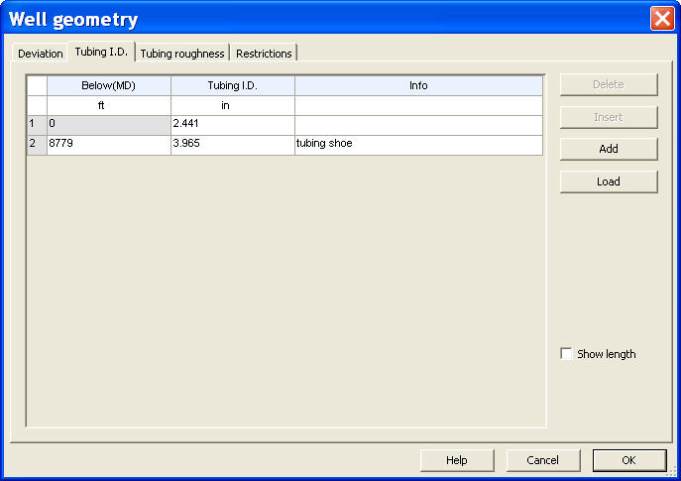
diameters, depths and relevant information:
-
A
2.441 in
tubing from
0
to
8779 ft
(MD).
-
A
3.965 in
casing from
8779
to
12650 ft
(MD).
Fig. B01.2 • Loading depths and IDs
Check ‘Show length’ for verifying the data.
Some comments can be added in the info lines as ‘tubing shoe’ line 2. These comments will
appear in the plot representing the fluid path (see Fig. B01.4 below).
Once done, exit with OK.