Basic HTML Version


Ecrin v4.12 - Doc v4.12.02 - © KAPPA 1988-2009
Amethyste Guided Session #1
• Ame
GS01 - 11/19
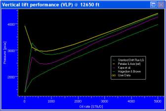
Fig. C01.8 • VLP plot with 4 correlations
D01 • Inflow Performance Relationship
The selection of the model defining the outflow is now done. The next step is to define the
inflow model for analysis, Inflow Performance Relationship (IPR).
Minimize the VLP plot and click on the IPR icon
. The following window opens:
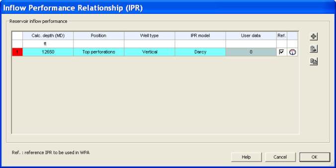
Fig. D01.1 • IPR window
The first time entering this dialog, a default IPR model is selected at the well bottom hole
depth (if defined). The active row in the grid is highlighted in blue and the red cell indicates
that the IPR model is not correctly defined yet. When several IPRs are created for comparison,
this red mark helps to differentiate between well defined IPR models and others. In this case,
the IPR set as reference is the one that will be used in the Well Performance Analysis.
Modify the calculation depth
to
12582 ft
. Select
‘Top perforations’
for the Position label. A
calculation node will be automatically added, at the corresponding depth, into the list of VLP
calculation nodes.