Basic HTML Version


Ecrin v4.12 - Doc v4.12.02 - © KAPPA 1988-2009
Topaze Guided Session #2
•
TopGS02 - 2/12
As the objective of this section is to illustrate the use of the 2D Map only we will not load a
production history.
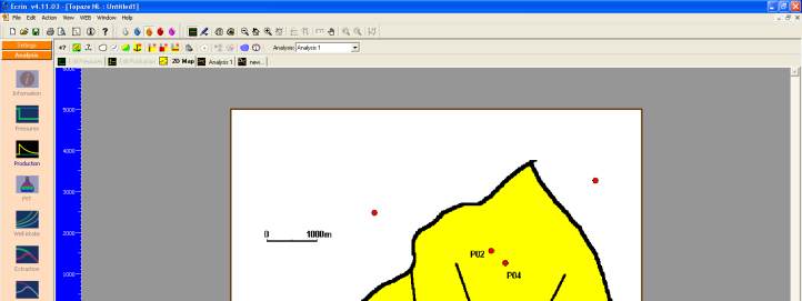
In the 2D Map toolbar, click on
and expand the bitmap sub-menu to load the bitmap file
TopGS02_FieldMap.bmp ( ). Note that most of the 2DMap options displayed in the toolbar
are also accessible through the popup menu available with a right click in the 2D Map area.
Fig. B01.2 • Load bitmap
Move the tested (reference) well to P01 using the mouse. The use of the bitmap is to help you
defining contours, other wells, faults and setting the scale.
Define the other vertical wells using the icon . Hit each time you want to add a well and
click in the 2D Map area to position the newly created well as shown on the bitmap. Fractured
and horizontal wells can also be defined using the toolbar or the popup menu.
Define P03 as a fractured well, clicking once to set one end of the fracture and clicking a
second time to set the other end of the fracture.
The position of the well can be changed interactively afterwards using the mouse. By clicking
on the well, the fracture length and orientation can again be changed. Double clicking on the
well gives the exact fracture half length and orientation.
Double click on each well to change the name in the Well dialog to the appropriate well name
indicated on the bitmap – we do not need to change any other parameter at this stage. Note
that the choice of the tested well (the well carrying the pressure gauge on which the
interpretation will be conducted) can be modified and that any well can be excluded from any
consequent model generation or simulation.