Basic HTML Version


Ecrin v4.12 - Doc 12.02 - © KAPPA 1988-2009
Rubis Guided Session #1
• Rub
GS01 - 4/33
v4.
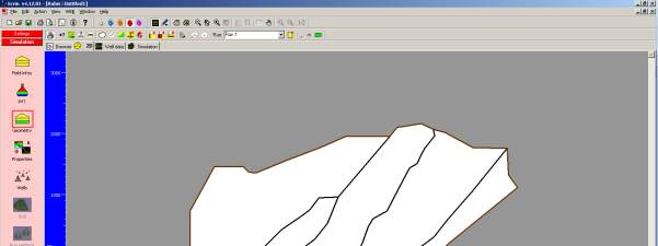
Next, draw the contour ( ) to fit the limits indicated by the field image. Starting anywhere
on the contour, proceed around the reservoir by moving the mouse and clicking until the
“rubber band” of the overlaid trace is complete. Double click to finish. Finally we will draw the
sealing faults indicated as inner black lines on the bitmap. Click on
and use exactly the
same technique used to draw the contour.
When the contour and the faults are created hide the bitmap by selecting the option “show
nothing” in the display settings ( ) in order to visualize the current top view of the reservoir:
Fig. B02.3 • 2DMap after contour and faults creation
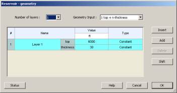
B02.2 • Reservoir Vertical Definition: Defining the Layers
We will now complete the definition of the reservoir shape by setting the number of layers as
well as the individual layer horizons. This is achieved in the “Geometry”
option
available in the Simulation page, which calls the “Reservoir – Geometry” dialog:
Fig. B02.4 • “Reservoir - Geometry” dialog