Basic HTML Version


Ecrin v4.12 - Doc v4.12.02 - © KAPPA 1988-2009
Saphir Guided Session #3
•
SapGS03 - 9/13
The difference between the homogeneous and the (radial) composite numerical model can
be observed.
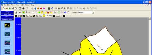
In the 2D Map, the 'white' zone corresponds to the pressure and time matches and is the
reference. The M and D ratios are then: (white zone)/(colored zone). Setting the Composite
anchor outside the circle surrounding the well defines the composite system with the same
convention as the analytical model, the M and D ratio are: (inner condition)/(outer condition).
D01.2 • Composite reservoir
Select the
tab again, and choose to draw two new faults cutting the reservoir in
three zones as illustrated in Figure D01.2 left. The new zones are colored white indicating that
the mobility and diffusivity have not been set and are equal to the mobility and the diffusivity
of the radial composite well.
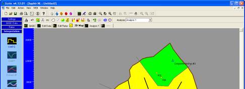
Drop a composite anchor in each of the new zones. This will change the color of the zones and
enable the setting of M and D in the numerical model for regeneration of the model response.
Figure D01.2 right. In order for these reservoir zones to be taken into account in the model the
faults separating them from the central reservoir have to be fully or partially leaky.
Double click on each fault and change the leakage factor to
0.5
.
Fig. D01.2 • Composite reservoir
Note that in this session we will keep no flow boundary conditions on all segments of the
contour. However it is possible to easily set any segment to constant pressure in the contour
edition dialog (tab
), accessible by a double click on the contour.